The weekend of June 23-24, 2024 took place in Paris, the meeting around the MSX standard:

the opportunity to meet around standard MSX and to compare our achievements with those of others.
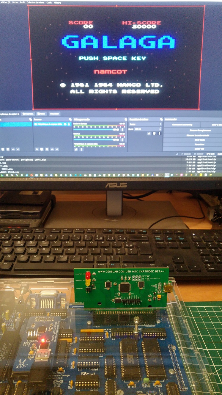
I was also able to carry out some tests of my USB cartridge and found that it works well, except on the Panasonic FS-A1. The 48K cartridges seem not to want to launch after loading, although it works very well on my Omega and other machines.
So, I looked a little closer at this FS-A1 and noticed that its bios has some particularities which encourage some owners to replace it with a 'minimal' version. I will investigate this aspect, knowing that the cartridges which did not start on the Panasonic, work without problem on my Omega, without having touched it in the slightest, that is to say with the cartridge loaded with the ROM which did not start on the Panasonic!
Mr. Kazuhico Nishi was present at this MSX day. For those who don't know Mr. Nishi, he is the person who created the MSX standard with Mr Gates, in the early 80s.

No need to make introductions...
Mr. Nishi presented his MSX0 and MSX3 to us.
So if I understood everything correctly, because I had never managed to understand what was going on since I saw articles on these machines, it would in fact be two machines based on the compiled MSX basic. Obviously these two machines offer an MSX compatible hardware environment, but based on an emulator.
Msx0 would be more specifically dedicated to IOT, while MSX3 would be adapted to computer learning. These two machines are therefore two somewhat dedicated hardware emulators based on a fast processor but I don't know what processor it is.
 |
| MSX0 |
 |
| MSX3 |
Well, until now I hadn't really understood the subject, and I was telling myself somewhere that I didn't really see the point of such a machine. Well now I know that these two machines are of absolutely no interest, sorry Mr. Nishi.
How to say, IOT is... dead! And learn computer science, in France, today, it's python, and that's all. so ok...
Nevertheless, I had the unspeakable honor of posing in the group photo with Mr. Nishi.
For me, the loop is complete. When I discovered microcomputers in the early 80s, people like Gates, Tramiel, Sinclair, Jobs, Woz and the others were simply geniuses and people living in a galaxy other than mine. I was fifteen years old and the future was just beautiful.
Obviously, since then, the reality here, in France, a small country with no future since a long time, my future has been completely different than the one imagined.
Come on, at least I feel like I was a little part of the story...

Those who know me will recognize me ;-)
Thanks to MSX Village for this very nice moment.